Make sure the computer is turned off before you start taking it apart.
ACCESSING MAIN PARTS UNDER THE BOTTOM COVER.
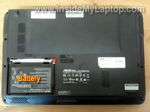
Remove the battery.
Remove one screw securing the bottom cover.
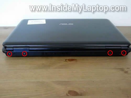
Remove four screws securing the bottom cover on the back side.
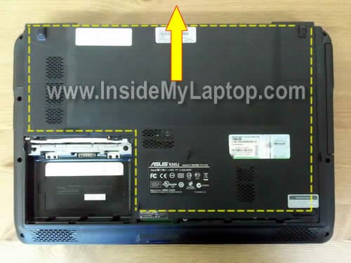
Slide the bottom cover to the shown direction.
Remove the bottom cover.
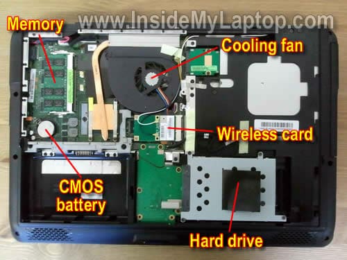
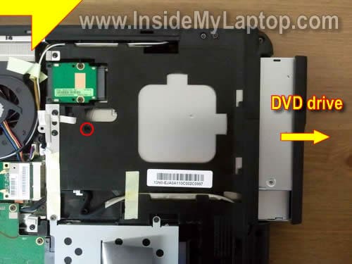
Under the bottom cover you’ll get an easy access to the memory module, hard drive, CMOS battery, cooling fan, DVD drive, wireless card and heat sink with processor.
Remove one screw securing the DVD dirve.
Slide the DVD drive to the right and remove it.
Remove four screws securing the hard drive assembly.
Slide the hard drive assembly to the right to disconnect it from the connector on motherboard.
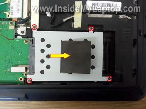
Remove the hard drive assembly.
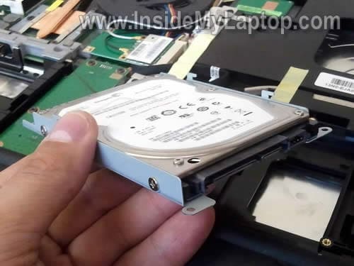
Now you can separate the HDD from the caddy and replace it with a new one if needed. As you see, it’s a regular 2.5″ SATA HDD.
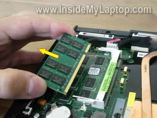
Spread latches on both sides of the memory module and after the module pops up at a 30 degree angle, carefully pull it from the slot by the edges.
In this particular notebook I found only one memory slot. It looks like some memory was integrated into the motherboard.
I’m not sure if all Asus K series notebooks have only one memory slot.
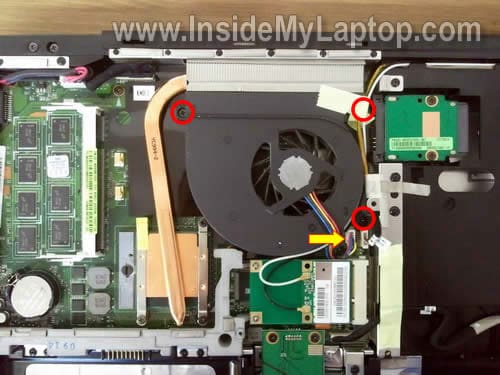
Remove three screws securing the cooling fan.
Unplug fan cable from the motherboard.
Now you can remove the fan.
REMOVING KEYBOARD.
In order to remove the keyboard it’s not necessary to go though all previous disassembly steps.
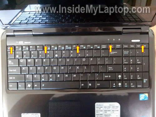
There are five small spring loaded latches securing the keyboard.
I pointed to them with yellow arrows.
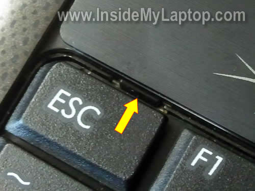
In order to unlock the latch, simply press on it with a sharp object.
At the same time pull the keyboard upwards.
After all latches unlocked, you can lift up the keyboard as it shown on the picture below.
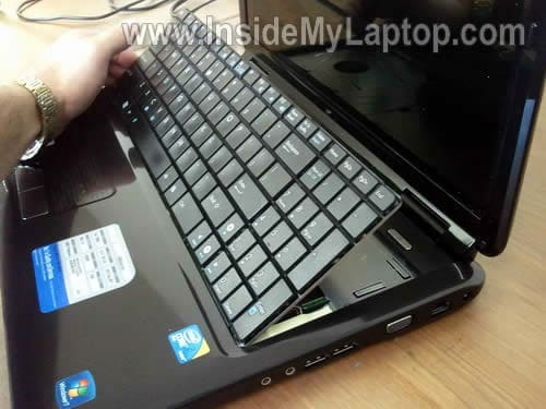
Carefully place the keyboard upside down on the palm rest.
Before you can remove the cable, you have to unlock the connector.
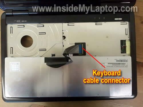
The keyboard cable is jammed between the white connector base and brown locking clip.
On the following picture the connector is shown in locked position.
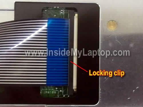
Move the locking clip about 2 millimeters to the left (do not move any further).
The locking clip must stay attached to the white base.
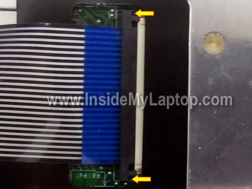
On the following picture the connector is shown in unlocked position. Now you can pull the cable from the connector.
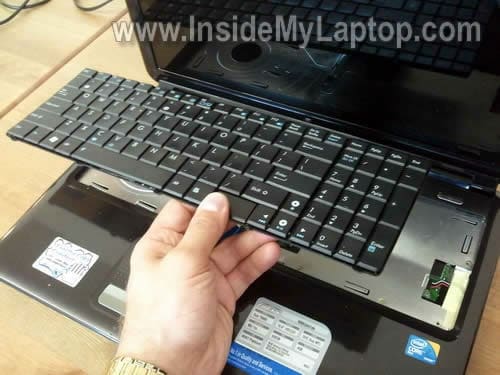
Finally, remove the keyboard and replace it with a new one if needed.
|


 發表於 2015-8-29 19:53:52

 QQ好友和群
 QQ空間
QQ空間 騰訊微博
騰訊微博 騰訊朋友
騰訊朋友 收藏
收藏 轉播
轉播 分享
分享 淘帖
淘帖